[Download 33+] Electrical Circuit Diagram Of A Rectifying Circuit
Get Images Library Photos and Pictures. Full Wave Rectifier Theory Circuit Working And Ripple Factor Rectifier Wikipedia Half Wave Rectifier Principle Working Dictionary Of Electronic And Engineering Terms Full Wave Rectifier Circuit
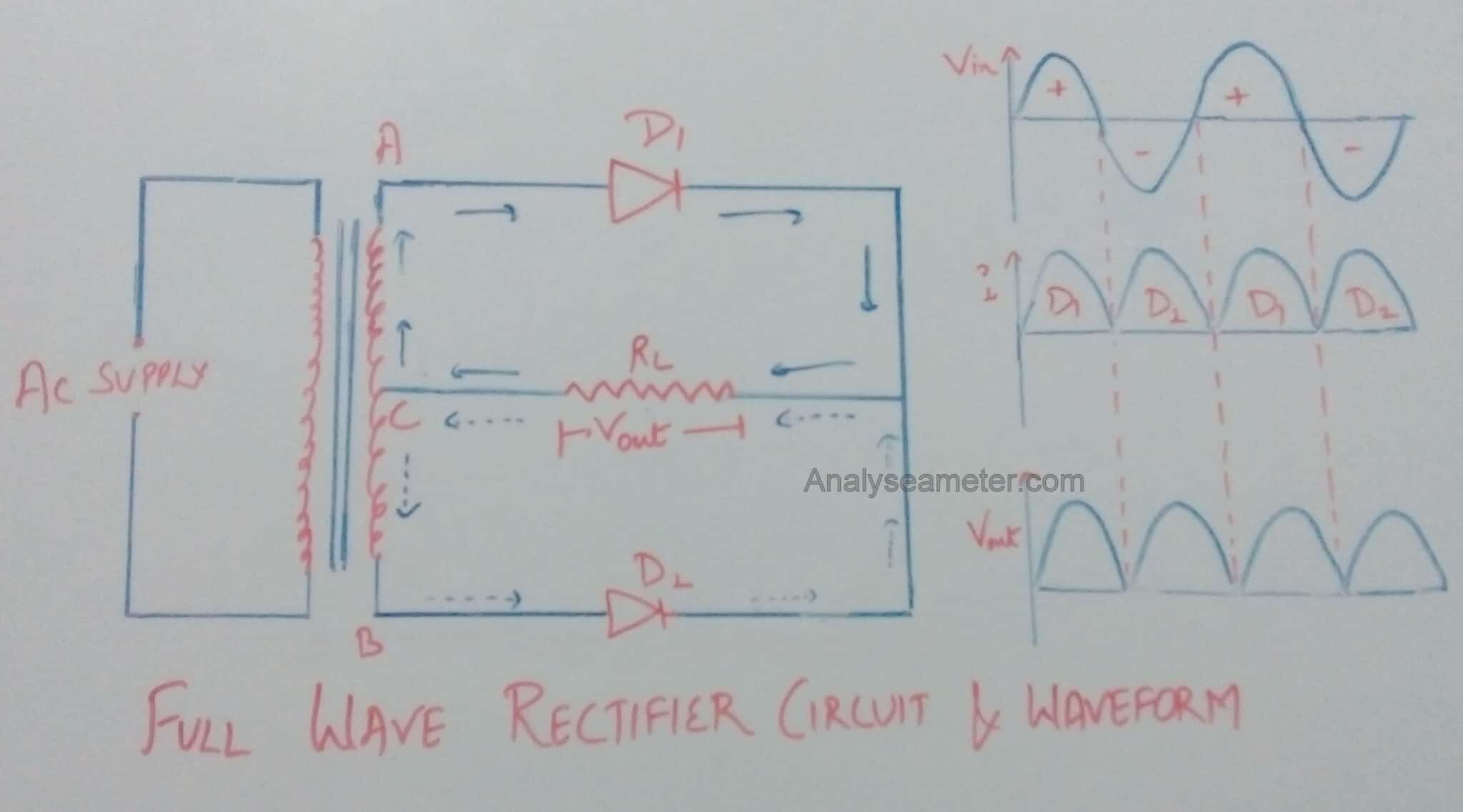
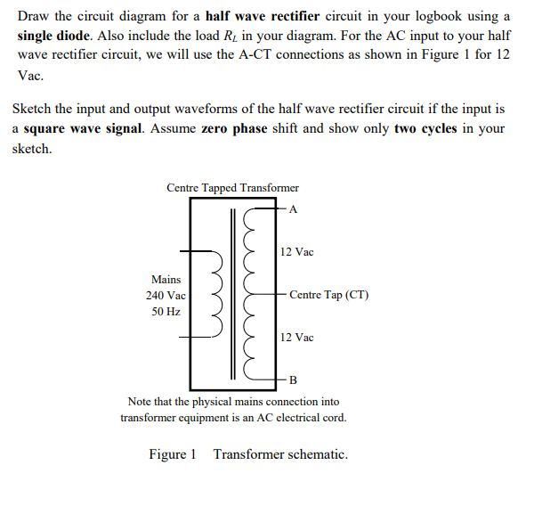
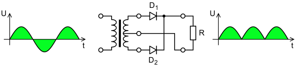
The simple half wave rectifier circuit diagram is shown in figure 1. Figure 3 circuit diagram of a full wave rectifier and its output voltage.
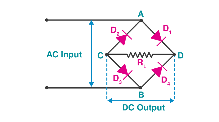
. Bridge Rectifier With Filter Schematic Diagram For A Full Wave Bridge Rectifier 4 Diodes In A Square Configuration Will Change Ac To Dc As Diode Drone For Sale Dc Circuit First Time Flyer Half Wave Rectifier Circuit Working Its Characteristics
 Full Wave Rectifier Circuit Characteristics Advantages Disadvantages Analyse A Meter
Full Wave Rectifier Circuit Characteristics Advantages Disadvantages Analyse A Meter Typically about 07 volts per diode.
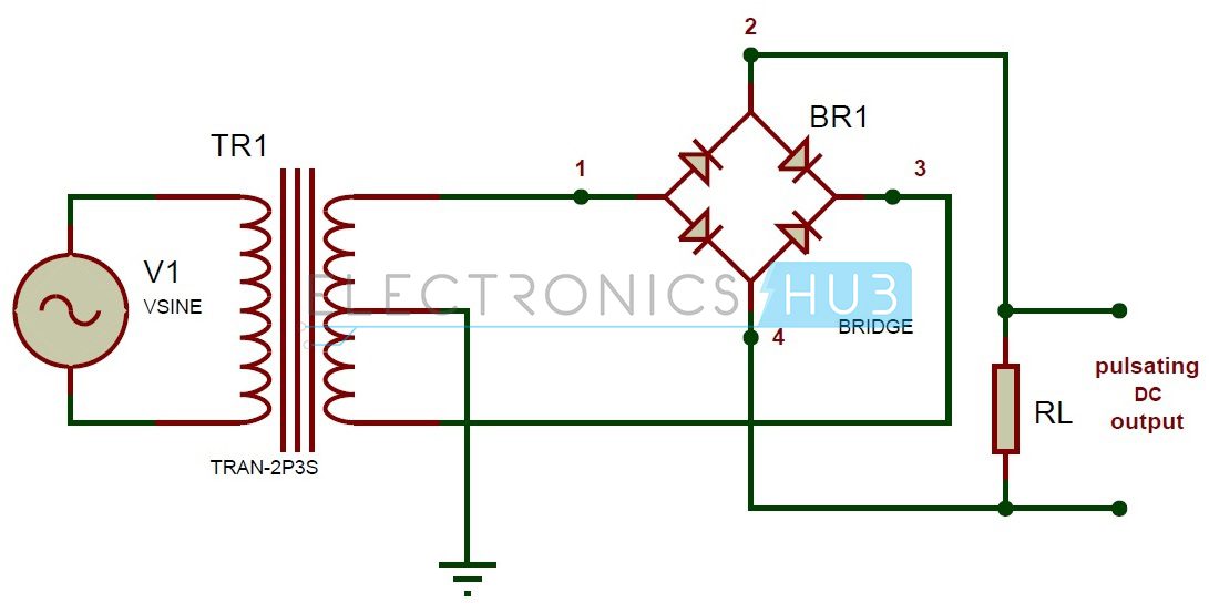
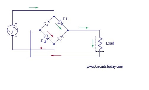
. The forward biasing and reverse biasing conditions of the diode makes the rectification. A half wave rectifier circuit diagram. Since youre using a br youre always going through two diodes at any given time.
The reason for the lower voltage is because the diodes have a forward voltage and will drop that much of the voltage. In bridge rectifier voltage that is given as the input can be from any source. In this article we are using a 6 0.
It can be from a transformer that is used to step up or down the voltage or it can be from the mains of our domestic power supply. An alternating current has the property to change its state. A simple pn junction diode acts as a rectifier.
The divisors are 2 rather than 2 because no power is delivered on the negative half cycle thus. In other circuits like filament heater circuits in vacuum tube electronics where the load is almost entirely resistive smoothing circuitry may be omitted because resistors dissipate both ac and dc powerso no power is lost. Electronic circuits rectifiers.
Note that we have used the common way of showing electronic circuits. For a half wave rectifier the ratio is very modest. Remembering the proper layout of diodes in a full wave bridge rectifier circuit can often be frustrating to the new student of electronics.
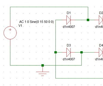
Rectifying the sine wave and putting a capacitor on that circuit you can collect and store about 15 12 volts. This unique arrangement gives the converter its name. The current through a load connected to a full wave rectifier or a bridge rectifier flows in one direction only as if all negative half cycles of the alternating current are converted to.
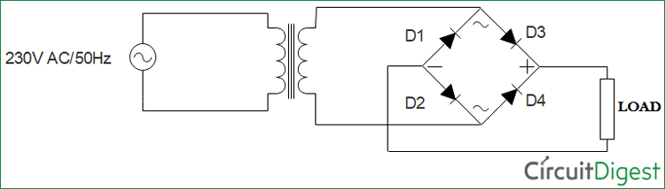
Whenever there arises the need to convert an ac to dc power a rectifier circuit comes for the rescue. From the circuit diagram it is apparent that the diodes are connected in a particular fashion. When the input voltage is on its positive half cycle the diode conducts the diode is placed in forward bias current flows and a voltage appears across the load resistor.
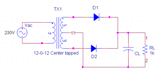
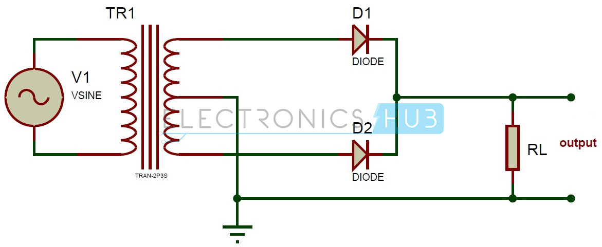
The transformer also provides electrical. The center tapped transformer supplies out of phase voltages to the two diodes. Ive found that an alternative representation of this circuit is easier both to remember and to comprehend.
Alternative full wave bridge rectifier circuit diagram. A typical dc power supply the transformer is used to step down the ac mains voltage 230v 50 hz to desired voltage level by controlling the turns ratio n2n1. Hence 07 x 2 14 forward volts dropped.
A full wave rectifier is an electrical circuit containing two diodes and a center tapped transformer used to produce pulsating dc. Its the exact same circuit except all diodes are drawn in a horizontal attitude all. Dc power supplies which are used to power electronic systems and circuits.
The block diagram of a typical dc power supply is shown in fig1. Thus the current path is completed through the ground. During the negative half cycle the diode is reverse biased and does not conductthere is no current in the circuit and no.
The secondary voltage v s is 230n2n1.
 Solved Draw The Circuit Diagram For A Half Wave Rectifier Chegg Com
 Half Wave Rectifier Circuit With And Without Filter Circuit Circuit Diagram Electronics Circuit
 Rectifier Circuits Diodes And Rectifiers Electronics Textbook
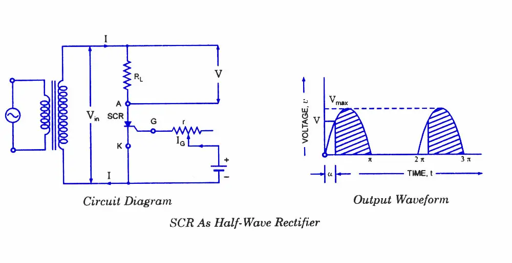
 Analysis Of Silicon Controlled Rectifier Circuit Diagram
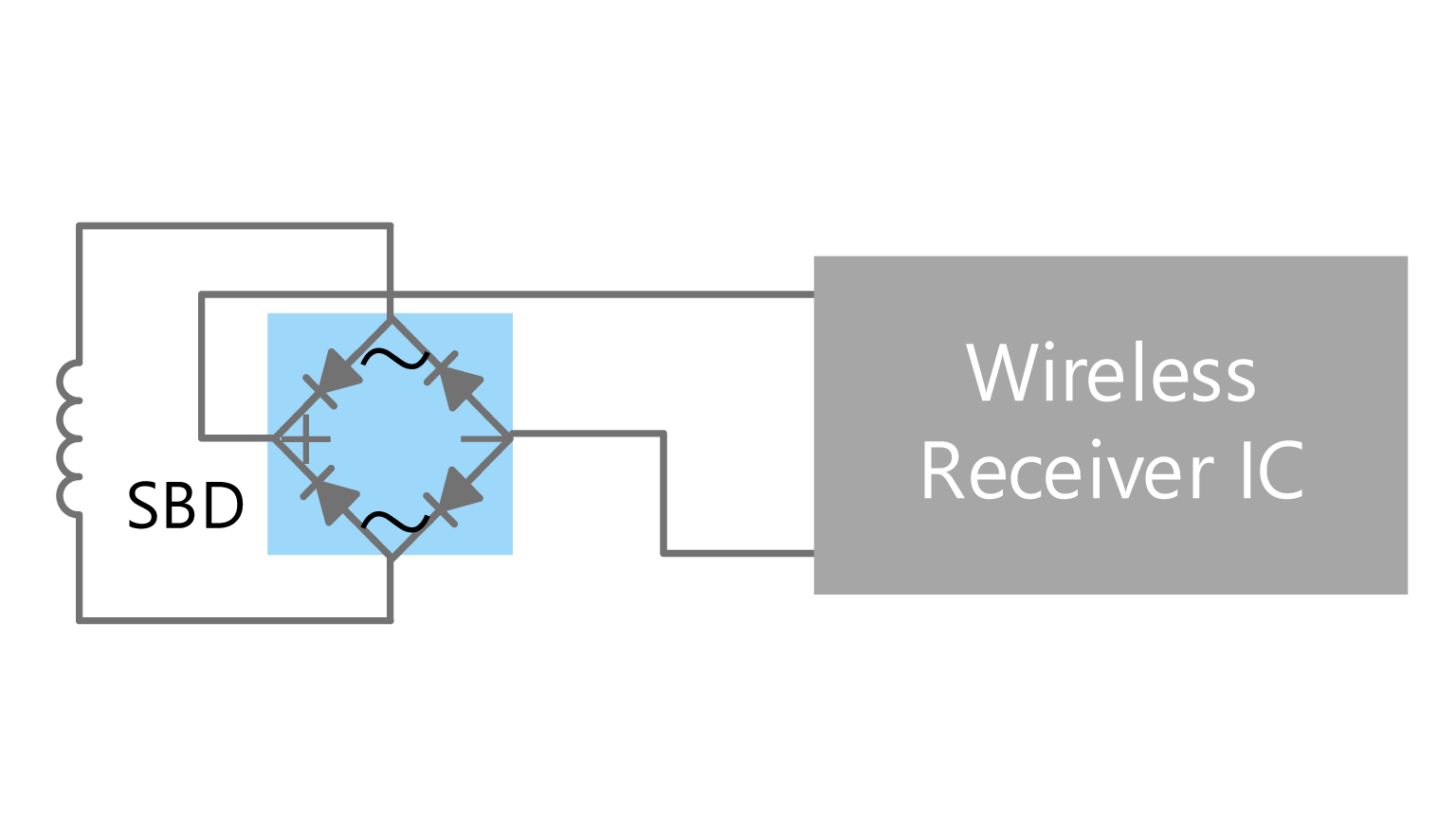 Wireless Power Supply Receiving Unit Rectifying Circuit Toshiba Electronic Devices Storage Corporation Asia English
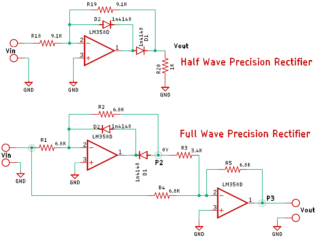 Half Wave And Full Wave Precision Rectifier Circuit Using Op Amp
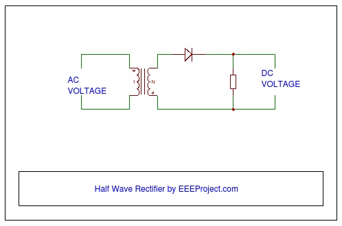 Half Wave Rectifier Principle Working

Https Www Toppr Com Ask Question Draw The Circuit Diagram Of Fullwave Rectifier Using Two Pn Junction Diodes And Explain Its
 Full Wave Rectifier Youtube
 Full Wave Rectifier Circuit Working And Theory
Electrical Circuit Of A Simple Transistor Ac Dc Rectifier In The Download Scientific Diagram
 Full Wave Rectifier Circuit Diagram Center Tapped Bridge Rectifier
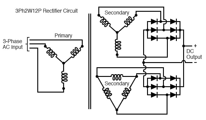
 Rectification Of A Three Phase Supply Using Diodes
 Full Wave Rectifier Circuit Through Bridge Rectification 5 Steps With Pictures Instructables
 Full Wave Rectifier Bridge Rectifier Circuit Diagram With Design Theory
 Bridge Rectifier Construction Working Advantages
 Full Wave Rectifier And Bridge Rectifier Theory
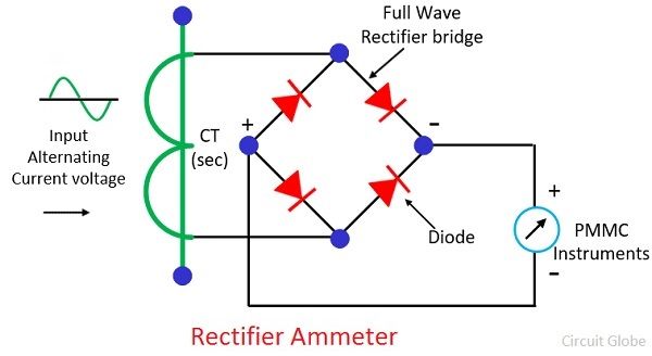 What Is A Rectifier Ammeter Advantages Explanation Circuit Globe
 Full Wave Rectifier With Filter Electronic Schematics Electronics Circuit Tech Updates
 Rectifier Circuits Diodes And Rectifiers Electronics Textbook
1
 Full Wave Rectifier Theory Circuit Working And Ripple Factor
 Rectifier Wikipedia


Comments
Post a Comment